

Does The Amount Of Mass Entering A Control Volume
- two.5.1 Conservation of mass
- two.v.2 Conservation of energy
- 2.v.3 Stagnation Temperature and Stagnation Enthalpy
- 2.v.3.1 Frame dependence of stagnation quantities
- ii.five.iii.2 Instance
- 2.five.3.three Steady Flow Free energy Equation in terms of Stagnation Enthalpy
- 2.5.iv Example Applications of the First Law of Thermodynamics
- 2.5.4.1 Tank Filling
- 2.5.4.two Period through a rocket nozzle
- two.5.4.three Power to bulldoze a gas turbine compressor
2.5 Command volume grade of the conservation laws
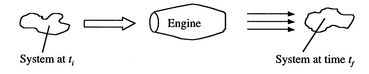
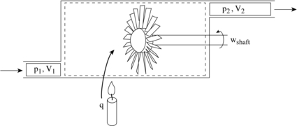
[VWB&S, 6.1, vi.2] The thermodynamic laws (as well equally Newton'due south laws) are for a organisation, a specific quantity of matter. More than often, in propulsion and power problems, we are interested in what happens in a fixed book, for instance a rocket motor or a jet engine through which mass is flowing at a certain rate. We may also exist interested in the rates of heat and work into and out of a system. For this reason, the control volume grade of the arrangement laws is of nifty importance. A schematic of the difference is shown in Figure 2.8. Rather than focus on a particle of mass which moves through the engine, it is more convenient to focus on the volume occupied past the engine. This requires us to employ the control volume class of the thermodynamic laws, developed beneath.
| |
2.5.ane Conservation of mass
For the control volume shown, the rate of change of mass within the book is given by the difference between the mass flow charge per unit in and the mass period rate out. For a single menstruation coming in and a unmarried flow coming out this is
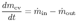 |
If the mass within the control volume changes with time information technology is because some mass is added or some is taken out. In the special case of a steady catamenia,
| |
| |
2.v.2 Conservation of energy
The commencement police of thermodynamics tin be written as a rate equation:
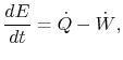
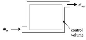
To derive the first law every bit a rate equation for a control volume we proceed as with the mass conservation equation. The physical idea is that whatever rate of change of free energy in the control volume must be caused past the rates of energy flow into or out of the volume. The estrus transfer and the work are already included and the but other contribution must be associated with the mass flow in and out, which carries energy with it. Figure 2.10 shows two schematics of this idea. The desired form of the equation will be
| [Elementary] |
 [More than General]
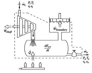
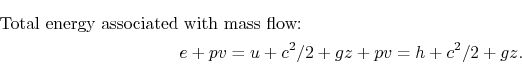
The fluid that enters or leaves has an amount of free energy per unit of measurement mass given by
![]()
![]()
![]()
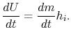
Including all possible energy flows (heat, shaft work, shear work, piston work, etc.), the first constabulary can then be written as:

We tin so combine the specific internal energy term, ![]() , in
, in ![]() and the specific flow piece of work term,
and the specific flow piece of work term, ![]() , to make the enthalpy announced:
, to make the enthalpy announced:
Thus, the first law can be written every bit:

For near of the applications in this course, there volition exist no shear piece of work and no piston piece of work. Hence, the outset constabulary for a command volume will be most often used equally:
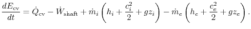 | (ii..ten) |
Note how our use of enthalpy has simplified the rate of work term. In writing the command book form of the equation we have assumed only i entering and one leaving stream, but this could be generalized to any number of inlet and exit streams.
In the special instance of a steady-land menstruum,
 |
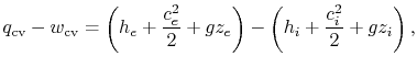
Applying this to Equation two.10 produces a form of the ``Steady Catamenia Energy Equation'' (SFEE),
![$\displaystyle \dot{Q}_{\textrm{cv}} - \dot{W}_{\textrm{cv}} = \dot{m}\left[\left(h_e+\frac{c_e^2}{2}+gz_e\right)-\left(h_i+\frac{c_i^2}{2}+gz_i\right)\right],$](https://web.mit.edu/16.unified/www/FALL/thermodynamics/notes/img263.png) | (2..eleven) |
which has units of Joules per second. We could too carve up by the mass flow to produce
 |
which has units of Joules per 2d per kilogram. For problems of interest in aerospace applications the velocities are high and the term that is associated with changes in the elevation is small-scale. From now on, we will neglect the
Dingy Points
What is shaft work? (MP 2.5)
What distinguishes shaft work from other works? (MP 2.6)
Definition of a control volume (MP 2.7)
2.5.three Stagnation Temperature and Stagnation Enthalpy
Suppose that our steady menstruum control book is a set of streamlines describing the flow up to the nose of a blunt object, as in Figure ii.xi.
| |
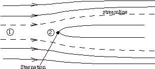
The streamlines are stationary in space, so there is no external work done on the fluid equally it flows. If at that place is also no heat transferred to the menstruation (adiabatic), and then the steady menses energy equation becomes
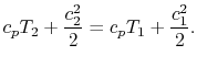 |
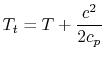
The quantity that is conserved is defined equally the stagnation temperature,
where
Information technology is also convenient to ascertain the stagnation enthalpy,
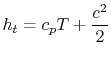 |
which allows united states to write the Steady Menstruum Energy Equation in a simpler form equally
| |
Note that for a quasi-static adiabatic process
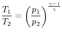 |
then we can write
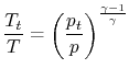 |
and define the human relationship between stagnation pressure level and static pressure level as
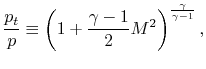 |
where, the stagnation pressure is the pressure that the fluid would reach if it were brought to goose egg speed, via a steady, adiabatic, quasi-static procedure with no external work.
2.5.iii.ane Frame dependence of stagnation quantities
An area of mutual defoliation is the frame dependence of stagnation quantities. The stagnation temperature and stagnation pressure are the atmospheric condition the fluid would reach if it were brought to naught speed relative to some reference frame, via a steady adiabatic process with no external work (for stagnation temperature) or a steady, adiabatic, reversible process with no external piece of work (for stagnation pressure). Depending on the speed of the reference frame the stagnation quantities will take on different values.
For instance, consider a high speed reentry vehicle traveling through the notwithstanding temper, which is at temperature, ![]() . Let'southward identify our reference frame on the vehicle and stagnate a fluid particle on the nose of the vehicle (conveying it along with the vehicle and thus essentially giving information technology kinetic energy). The stagnation temperature of the air in the vehicle frame is
. Let'southward identify our reference frame on the vehicle and stagnate a fluid particle on the nose of the vehicle (conveying it along with the vehicle and thus essentially giving information technology kinetic energy). The stagnation temperature of the air in the vehicle frame is
 |
where
The confusion comes about because ![]() is usually referred to as the static temperature. In common linguistic communication this has a similar significant every bit ``stagnation,'' but in fluid mechanics and thermodynamics static is used to label the thermodynamic backdrop of the gas (
is usually referred to as the static temperature. In common linguistic communication this has a similar significant every bit ``stagnation,'' but in fluid mechanics and thermodynamics static is used to label the thermodynamic backdrop of the gas ( ![]() ,
, ![]() , etc.), and these are not frame dependent.
, etc.), and these are not frame dependent.
Thus in our re-entry vehicle example, looking at the still atmosphere from the vehicle frame we run into a stagnation temperature hotter than the atmospheric (static) temperature. If we expect at the same still atmosphere from a stationary frame, the stagnation temperature is the same equally the static temperature.
2.5.three.2 Example
For the case shown below, a jet engine is sitting motionless on the ground prior to accept-off. Air is entrained into the engine by the compressor. The inlet tin exist assumed to be frictionless and adiabatic.
| |
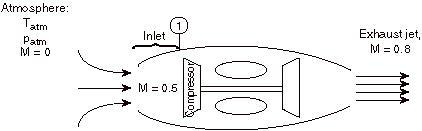
Considering the state of the gas within the inlet, prior to passage into the compressor, every bit state (1), and working in the reference frame of the motionless plane:
- Is
 greater than, less than, or equal to
  ?
? The stagnation temperature of the temper,
 , is equal to since it is moving the same speed as the reference frame (the motionless airplane). The steady flow energy equation tells usa that if there is no heat or shaft piece of work (the example for our adiabatic inlet) the stagnation enthalpy (and thus stagnation temperature for abiding
  ) remains unchanged. Thus
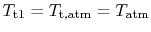
- Is
 greater than, less than, or equal to ?
 If
 then
then  since the flow is moving at station 1 and therefore some of the full energy is composed of kinetic energy (at the expense of internal free energy, thus lowering )
 - Is
 greater than, less than, or equal to
  ?
? Equal, by the same argument every bit i.
- Is
 greater than, less than, or equal to ?
 Less than, by the aforementioned argument as 2.
2.v.3.iii Steady Flow Free energy Equation in terms of Stagnation Enthalpy
The form of the ``Steady Flow Free energy Equation'' (SFEE) that we will most commonly use is Equation two.eleven written in terms of stagnation quantities, and neglecting chemical and potential energies,
![]()
Muddy Points
What is the difference betwixt enthalpy and stagnation enthalpy? (MP 2.8)
2.5.four Example Applications of the Beginning Law of Thermodynamics
[VW, S& B: 6.four]
2.v.4.i Tank Filling
Using what nosotros have just learned we can assail the tank filling problem solved in Section 2.3.3 from an alternating betoken of view using the control volume form of the first law. In this problem the shaft piece of work is zero, and the heat transfer, kinetic energy changes, and potential energy changes are neglected. In addition there is no go out mass flow.
| |
The control volume class of the first law is therefore


2.v.4.2 Menstruum through a rocket nozzle
A liquid bi-propellant rocket consists of a thrust chamber and nozzle and some means for forcing the liquid propellants into the chamber where they react, converting chemic energy to thermal energy.
| |
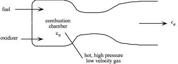
One time the rocket is operating nosotros can assume that all of the menstruum processes are steady, so information technology is appropriate to use the steady period energy equation. Besides, for now nosotros will assume that the gas behaves as a perfect gas with abiding specific heats, though in full general this is a poor approximation. At that place is no external work, and we assume that the flow is adiabatic. Nosotros define our control volume every bit going between location ![]() , in the chamber, and location
, in the chamber, and location ![]() , at the exit, and then write the First Constabulary as
, at the exit, and then write the First Constabulary as
| |
or
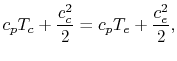 |
Therefore
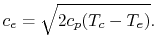 |
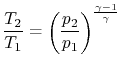
If we assume quasi-static, adiabatic expansion and so
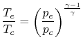 |
and then
![$\displaystyle c_e = \sqrt{2 c_p T_c \left[1 - \left(\frac{p_e}{p_c}\right)^{\frac{\gamma-1}{\gamma}}\right]}.$](https://web.mit.edu/16.unified/www/FALL/thermodynamics/notes/img300.png) |
2.5.4.iii Power to drive a gas turbine compressor
Consider for case the PW4084 pictured in Figure 2.15. The engine is designed to produce about 84,000 lbs of thrust at takeoff. The engine is a two-spool pattern. The fan and low pressure level compressor are driven by the depression pressure turbine. The high force per unit area compressor is driven by the loftier pressure turbine. We wish to discover the full shaft work required to drive the pinch system.
| |
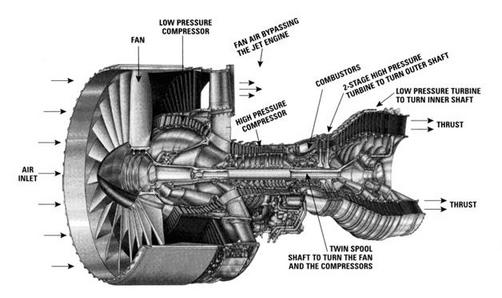
We ascertain our control volume to encompass the compression system, from the front end of the fan to the back of the fan and loftier force per unit area compressor, with the shaft cutting through the back side of the command book. Heat transfer from the gas streams is negligible, so we write the First Police force (steady flow energy equation) every bit:
 |
For this problem nosotros must consider 2 streams, the fan stream,
We obtain the temperature change by assuming that the pinch process is quasi-static and adiabatic,
 |
then
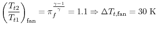 |
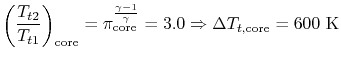 |
Substituting these values into the expression for the starting time law in a higher place, forth with estimates of
Annotation that

Does The Amount Of Mass Entering A Control Volume,
Source: https://web.mit.edu/16.unified/www/FALL/thermodynamics/notes/node19.html
Posted by: vereenwhising.blogspot.com
0 Response to "Does The Amount Of Mass Entering A Control Volume"
Post a Comment